Compliant wall-climbing robot
This research presents a new climbing robotic mechanism for high-payload climbing and wall-to-wall transitioning. Payload capacity and transition ability are very important in climbing-robot applications for heavy industries and construction industries. The proposed robotic platform consists of three magnetic tread-wheel modules that are connected by links with two compliant joints. The front compliant joints are passive type with a torsion spring, and the rear compliant joints are active type with torque-controlled motors. A torque-controlled tail is attached at the end of the third module. Various transitions are achieved by the compliant joints, which change shape depending on the external conditions. High payloads are achieved by the large contact area of three magnetic tread-wheel modules. Detailed design issues are presented with analysis of the design parameters. The robot can perform two internal and two external transitions against gravity and every possible transition in the side surface driving direction. The robot can carry 10 kg payloads on vertical surfaces and on a ceiling. The ability to overcome a 30 mm diameter obstacle on vertical surfaces is also verified by experiments. The proposed robotic platform is going to be used in heavy industries.
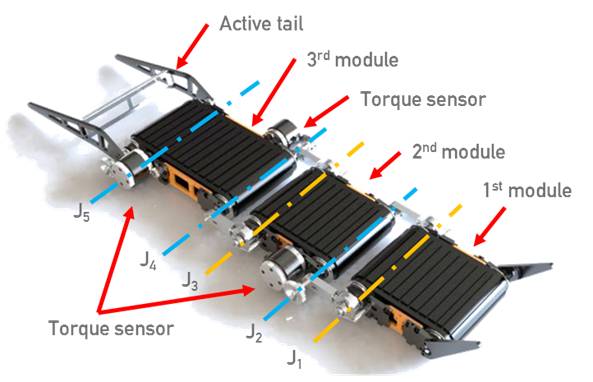
Fig 1. 3-D modeling of the Combot configuration
The detail specifications of Combot is following. First module = 2.8 kgf, second module = 2.8 kgf, third module = 4.5 kgf. The power of the motor is supplied by an external power supply. The robot and PC-based interface communicated through a USB cable device. The size of the Combot was 216 × 522 × 38 mm3, excluding the tail length, and the weight of the Combot was 6.4 kg, including battery, controller, torque sensor, and signal conditional.
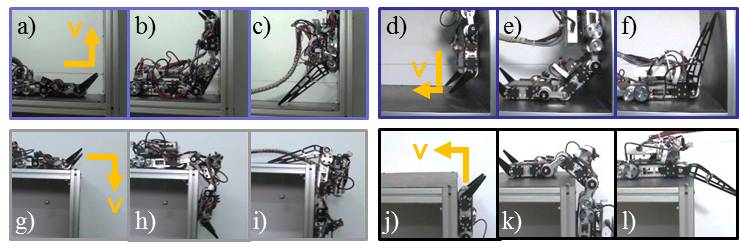
Fig 2. Photo snapshots during internal transitions: 0°–90° (a–c); 270°–0° (d–f);
Photo snapshots during external transitions: 0°–270° (g–i); 90°–0° (j–l);
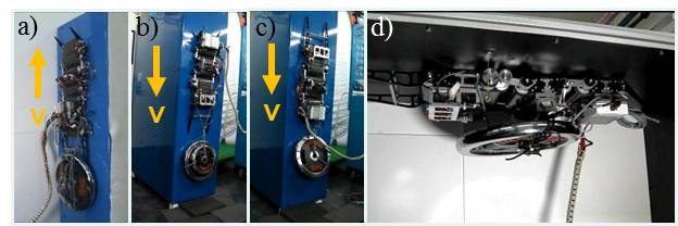
Fig 3. Photos of the vertical climbing (a) upward with 10 kg payload, (b) downward (reverse) with 15 kg payload, (c) downward with 10 kg payload, and (d) photo of 10 kg static payload capacity on a ceiling.
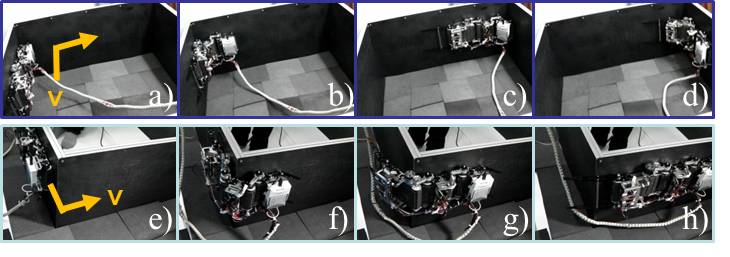
Fig 4. Photos of the side surface driving and transitioning (see also Multimedia Extension): internal transitioning (a–d); external transitioning (e–h).
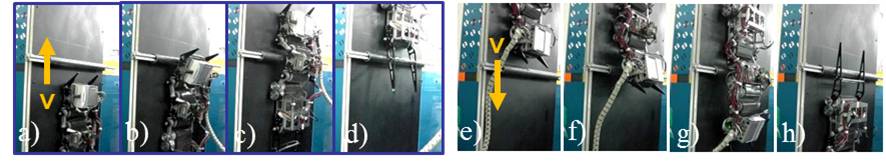
Fig 5. Photos of overcoming an obstacle on a vertical surface: upward direction (a–d); downward direction (e–h).